Latest Issue
 
Windtech International May June 2025 issue
 

Login


FOLLOW US AT

follow

 Follow us at BlueSkyFollow us at BlueSky


follow


New Welding and Inspection Methods
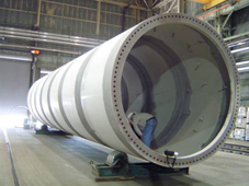
ImageConical cylinder wind turbine towers are classic examples of welding-dependent structures, where specialised shapes are desired at a large scale. Opportunities exist to increase production efficiency in welding by changing the submerged arc welding (SAW) procedures or by switching to another process, with tandem GMAW and laser hybrid as recommended alternatives. Tandem GMAW and laser hybrid would have advantages particularly when reorientation of parts is an important aspect of the fabrication effort. Phased-array ultrasonic inspection, which is already available for use in similar industries, can greatly increase the amount and quality of inspection information for gauging the importance of subsurface imperfections.

By William Mohr, Principal Engineer, EWI, USA .

{access view=!registered}Only logged in users can view the full text of the article.{/access}{access view=registered}

Tubular Tower
The tubular tower is built primarily from rolled plate and machined flange rings in dedicated facilities. These steel components are usually of commonly available structural steel grades and strengths, since higher strength, or specialised steel, gives little advantage in either fatigue performance for cyclic loading or for compressive buckling under peak loading. The largest welds in a tower are the long seams and girth welds. Girth welds are made both between adjacent cans and between a can and a flange, as shown in Figure 1. The door area welds in the bottom section of the tower can also be large, multipass weldments. The can plate can be rolled into a single ring that requires only one weld along the axial direction to make a closed ring. Thicknesses of can plate range from about 10mm to about 40mm thickness, increasing down the tower.

SAW Welding
The primary welding process for both long seams and girth seams is submerged arc welding (SAW). This process uses at least one electric arc to transfer heat and molten metal to a weld pool that solidifies and joins the adjacent pieces of steel. The arc is submerged under a blanket of granular flux that prevents the weld pool from being oxidised by the oxygen in the air. The productivity of the SAW process is high compared to other welding processes. With the large weld pool and the granular flux, the orientation of the welding must allow gravity to hold the weld metal and the flux in place. This requires reorientation of the parts to be joined. For instance, to weld the long seam from both inside and outside, the can must be reoriented between welding operations. The high productivity and hidden arc both push this process to high levels of automation compared to other welding processes.

Tandem SAW
A way of achieving higher productivity for automated welding is to add another welding torch feeding the same weld pool. A tandem arrangement, with the second torch following the first, increases both weld deposition and depth of fill. This increases the control complexity to maintain two arcs, but this can be automated so the welder need not control the arc interaction parameters.

SAW Opportunities
Submerged arc welding can be pushed to greater deposition rates by adding yet more torches to the same weld pool. Increasing the number of torches to four by pairing torches in a tandem arrangement gives a dual tandem arrangement. The increased deposition rate of dual tandem SAW allows faster travel speeds for the same depth of penetration. It also allows fewer passes to complete the same total deposition. The limitations of SAW for flux control, positioning and requirement for automation remain as the additional torches are added. Accuracy and repeatability of fit-up can be used to improve weld quality of SAW joints. While SAW provides fast deposition rate and good shielding under the flux, the resulting weld shapes can vary based on fit-up and process accuracy.

Tandem GMAW Opportunities
Gas metal arc welding (GMAW) also uses an arc to transfer heat and molten metal, but instead of a flux for shielding it uses an inert or at least unreactive gas. GMAW can be designed for additional productivity by pairing welding torches to add the weld metal to the same weld pool. This increase allows GMAW to compete in deposition rate and depth of fill with SAW. A specialised torch with two electrodes is shown in Figure 2. Tandem GMAW can use a tighter bevel than SAW, allowing the same deposition rate of weld metal to provide an increased rate of fill. It can also be used in more positions, avoiding reorientation required by SAW. As for SAW, stabilising two arcs requires automated controls.

Laser Hybrid Opportunities
Another approach to providing high productivity welding is to choose processes that achieve large thickness of joint in a single pass without requiring as much weld metal. A combination of laser beam and GMAW provides a relatively narrow weld, as is shown in the example in Figure 3. Laser hybrid is less orientation sensitive even than tandem GMAW and allows faster travel speed of the welding head. The speed is obtained with weld pool stability because each part of the hybrid process is stabilised by the other part. The narrow welds obtained by laser welding require good fit-up between the adjacent pieces, but can avoid a pre-machined bevel. Such accuracy of fit-up may be much tighter than the current fit-up for SAW, which may allow as much as a 6mm gap.

Approaches that give tighter fit-up may mean using weld positioning for advantage in fit-up, or cutting one of the mating parts with a laser to provide the desired accurate fit-up. The laser hybrid approach can accommodate the thickness transitions at girth welds often used in today’s designs. The breadth of the surface weld pool is widened from what laser alone would provide by the addition of the GMAW. Laser hybrid has an advantage in further limiting welding distortion compared to the arc processes discussed above, given the lower total heat input and the smaller amount of weld metal deposited.

Current Inspection
The current inspection practice for welds uses manual manipulation of ultrasonic transducers as the primary inspection method. The ultrasonic energy is input from a piezoelectric transducer and detected at that same transducer or a similar one. Since the welds are not ground flush to match the surface of the adjacent base metal, the transducer must be placed on the base metal surface to get good contact and use an angle beam to aim the ultrasonic energy at the weld area. Different angles are used because the response of the imperfection is measured as an amplitude of response and different amplitudes are observed based on the perpendicularity of the imperfection surface to the incoming ultrasonic beam. It is also important to use multiple angles to scan the full thickness of the weld.

Phased-Array Inspection
An ultrasonic inspection method that would improve detectability, repeatability and information transfer and recording is already available. Phased-array inspection uses multiple smaller piezoelectric transducers in an array pattern that can be timed to activate so that the ultrasonic beam can be scanned or focused. An example array transducer is shown in Figure 4.

Phased-Array Output
The output available from the phased-array inspection is similar to the output of other scanned ultrasound systems, such as those used for medical imaging, as shown in Figure 5. As can be seen in the left hand side of the figure, the same type of amplitude versus time scan currently obtained by the manual operator is also available. Nothing prevents an inspection by both the phased-array technique and the officially required manual procedure. This may be particularly valuable when in transition to a new welding process or procedure, because of the larger amount of information recorded by phased-array methods.

Biography of the Author
William Mohr is a Principal Engineer at EWI, where he has worked in welding design and structural integrity since 1993. His PhD from Stanford University was awarded in 1989. EWI is North America’s largest research institute for welding, joining and allied technologies.{/access}
 
Use of cookies

Windtech International wants to make your visit to our website as pleasant as possible. That is why we place cookies on your computer that remember your preferences. With anonymous information about your site use you also help us to improve the website. Of course we will ask for your permission first. Click Accept to use all functions of the Windtech International website.